
The control starts up in Incremental jog mode. In order to jog the axes in continuous movement, you need to press the INCR/CONT key to switch from incremental to continuous jog mode.
The machine is a three-axis vertical gantry mill. Axis movement is as follows:
| X | Table left/right below crossrail |
| Y | Carriage movement across crossrail |
| Z | Quill up/down from head |
In addition to the three servo axes, the crossrail (bridge) can be moved up and down using coarse and fine feed motors. There is no position control or position feedback for the crossrail movement.
The Machine Home position is with the table fully to the left; carriage away from the operator station (towards the tool changer); and quill all the way up.
|
The control starts up in Incremental jog mode. In order to jog the axes in continuous movement, you need to press the INCR/CONT key to switch from incremental to continuous jog mode. |
Tool descriptions and locations are stored in the Tool Library.
To get to the Tool Library, press F1/Setup → F2/Tool → F2/Tool Lib.
Tool height and diameter offsets are stored in the Offset Library.
To get to the Offset Library, press F1/Setup → F2/Tool → F1/Offset Lib.
The Centroid tool library has space in its list for up to 200 tools. Only the first 24 tools — T1 through T24 — can be used on the SNK RB-2N. Each tool must be in the carousel bin matching its tool number.
When you run a CNC program cycle, the program will generally call out the tools it needs, when it needs them, and the control system will change tools automatically.
During setup and manual operations, you may need to have the machine change tools (put the current tool away in the carousel, and get out a different one) outside of any CNC program.
You can do that in one of two ways:


To remove a tool:
To load a tool:
When you load and unload tools by hand as described above, the control system and PLC do not register any change. If the control previously expected that Tool 7 was in the spindle, and planned to put it away in carousel bin 7 upon the next tool change, then that is still what it will expect, and what it will do.
The SNK machine has a manual load station at the back of the carousel, where you can load and unload tools as needed.
To use the manual load station:
Generally, no special codes are required in your CNC programs in order to use the automatic tool changer. The same M6 code works for both manual and automatic tool changing.
To change to a new tool, program T__ M6. The control will pick up the new tool from the carousel, then put away the previous tool in its original carousel bin.
If an error occurs which causes the automatic tool change sequence to be interrupted, you will need to take a few steps to ensure that the control is ready to run again, before you can restart the job.
First, you will need to remove any tool that was left in the changer arm. If possible, you want to reverse the incomplete tool change sequence (putting the old tool back in the spindle, and the new tool back in the carousel). If that is not convenient, then remove both the old tool and the new tool from the machine until normal operation can be restored.
Next, you will need to return the tool changer components to their idle, "ready" positions:
If the arm or arm carrier is out of position, you can use the ATC Pendant to move it as needed.
If the carousel is not centered on a tool position, then use the Magazine Panel controls to move it into any aligned position, where it will lock in place.
When a tool change is interrupted before it can complete, the control will assume that no tool exchange has happened. It will assume that the previous tool is still in the spindle, and still needs to be put away in its corresponding carousel location.
If you removed one or both tools from the machine after the failed
tool change, then after moving the ATC components to their "ready" positoins,
you should return the previous tool to the spindle, and return the new
tool to its carousel location.
Troubleshooting Failures
If a tool change fails for any reason, the PLC will store the state of
numerous inputs and flags in word variable W8. Use the Alt-I PLC Diagnostic
display to view the value in W8.
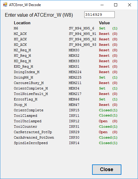
A separate program, named AWDecode.exe, is provided to interpret and display the content of W8. You can launch AWDecode.exe from the Windows start menu. Enter the value from variable W8 in the box at the top of the AWDecode window. AWDecode will then show the state of the various input and flag bits which the PLC program has stored.
This information, combined with the actual
error message which was displayed in the control's status window when the
failure occurred, will often show exactly what went wrong.
 The work lights
will come on automatically when the machine is powered up.
The work lights
will come on automatically when the machine is powered up.
You can turn the lights off and on by pressing the work light (Aux2) key on the jog panel.
You can control spindle rotation speed and direction manually with jog panel keys, or automatically with program codes.
The spindle must be in Auto mode in order to use programmed M and S codes. The spindle must be in Manual mode in order to use the jog panel keys.
 |
Switch between Auto and Manual control modes. |
In Manual mode, you can control operation and direction with these keys:
 |
Select spindle forward (CW) |
 |
Select spindle reverse (CCW) |
 |
Start spindle running |
 |
Stop spindle |
In Auto mode, you can control operation and direction with these codes:
| M3 | Start spindle forward (CW tool) |
| M4 | Start spindle reverse (CCW tool) |
| M5 | Stop spindle |
| Snnn | Set speed to nnn RPM |
In either mode, you can further control speed with these keys:
 |
Increase speed |
 |
Set speed to 100% of programmed speed (Auto mode) or to half of maximum speed (Manual mode) |
 |
Decrease speed |
The machine has a hydraulically shifted 2-speed transmission in the head.
Gear shifting may be done with Jog Panel keys or with M functions, either in a CNC program or at the MDI prompt:
M42 |
High range | (60-3000 RPM) |
 | ||
| M41 | Low range | (15-750 RPM) |
 | ||
| M49 | Shift to best range for programmed RPM |
In automatic operation, the M3 and M4 codes call M49 at every spindle start, automatically shifting ranges as needed.
You only need to enter M41 and M42 for manual operations.
M41 and M42 require that spindle control be in Auto mode. For use in Manual mode, switch to Auto; run the gear shift M function; and switch back to Manual.
In manual operations, it is possible to run slower than the minimum for each range
listed above. For example, the minimum possible speed in high
range is about 60 RPM. Thus extra shifting can be avoided, as
long as full torque is not required.
Axis Clamps
There are axis holding clamps on the Y and Z axes. You can apply and release the clamps with the following M functions:
M34 |
Clamp head (Y axis) |
M35 |
Unclamp head (Y axis) |
M46 |
Clamp quill (Z axis) |
M47 |
Unclamp quill (Z axis) |
When you apply an axis clamp with M34 or M46, the corresponding servo motor is disabled (powered off).
When you release an axis clamp with M35 or M47, the corresponding servo motor is reenabled (powered on)
If an axis is clamped in a program cycle, and not subsequently unclamped, then it will remain clamped even after the program cycle ends.
You can use the F3/MDI prompt to unclamp an axis that was left clamped after the end of a program cycle.
To use the clamps with an axis that must move during the CNC program cycle, you will need to write the appropriate codes into your CNC programs. For example, if you want to move the Z axis to depth for milling, and then want to use the clamp to hold it there, your program sequence would be something like this:
; various program startup codes
G1 Z-0.5 ; move Z axis to first depth
M46      ; clamp Z axis and remove servo power
; various codes to perform the desired machining
M47      ; unclamp Z axis and restore servo power
G1 Z-1.0 ; move Z axis to next depth
M46      ; clamp Z axis and remove servo power
; various codes to perform desired machining at second depth
M47      ; unclamp Z axis and restore servo power
;...
If you are writing your program with the Intercon conversational programming feature on the control, you can use Insert → Other → M&G Code to insert the axis clamp and unclamp M codes.
As of June 2021, the Y axis clamp solenoid (SOL5) is inoperative, so clamping of the Y axis is not possible.
The control will automatically operate the way lube pump periodically, when running automatic program cycles. The way lube system will not operate when the machine is idle, even if the hydraulic pump is running.
Machine Parameter 179 controls the interval between way lube cycles, and the operating time for a cycle. The hundreds place of the Parameter 179 value is the lube cycle interval in minutes. The tens and ones place is the run time in seconds. For example, a value of 2015 means to run the lube pumps for 15 seconds, every 20 minutes of program cycle time.
If the oil level in the way lube tank runs low, a Fault condition will result.
In normal operation, the Auxiliary keys on the jog panel have the following functions:
|
Shift to high gear range | |
Work Light Off/On |  |
Jog Crossrail Up |
 |
No function |  |
No function |  |
Select Fine (slow) or Coarse (fast) crossrail jogging |
|
Shift to low gear range |  |
No function |  |
Jog Crossrail Down |
 |
No function |  |
No function |  |
Maintenance Mode On/Off |
In addition to the console jog panel, the machine is equipped with a Centroid WMPG-4 wireless MPG handwheel pendant. The handwheel pendant can be used for axis jogging and for cycle start, feed hold, and spindle control.
To use the MPG pendant, first press its silver power button. The display on the pendant should show a copy of the DRO axis position display.
To move an axis using the handwheel:
The handwheel can also be used as a spindle speed override control, or as a feedrate override control.
To adjust spindle speed, turn the increment-select knob to SPIN, then turn the wheel CW to increase spindle speed, or CCW to decrease spindle speed.
To adjust feedrate, turn the increment-select knob to FEED, then turn the wheel CW to increase the feedrate override, or CCW to decrease the feedrate override.
NOTE: if you use the WMPG handwheel to change the feedrate override setting, this takes precedence over the position of the knob on the console jog panel. However, as soon as you turn the knob on the console jog panel again, then its setting will take over. This could cause an abrupt change in axis speed, especially if you had used the WPMG-4 wheel to turn the feedrate override down.
In addition to the MPG handwheel, the WMPG pendant has Cycle Start, Feed Hold, and Tool Check keys. These keys function the same as the equivalent keys on the main jog panel.
There are two axis jog keys: "JOG -" and "JOG +". These keys will jog whichever axis is selected with the axis-select switch, in a jog mode (FAST/SLOW) determined by the increment-select knob:
The "= 0" key may be used to set Part Zero (the WCS origin) at the current position. Select the axis to be set, then press "= 0" to set the part position on that axis to zero.
There are four customizable Macro keys. As of June 2021, none of the macro keys are assigned specific functions.
The WMPG pendant relies on a USB-connected wireless transceiver. This transceiver antenna sits on top of the console, and should be plugged into one of the console USB ports.
The WMPG pendant requires two AA batteries. The battery compartment
is on the back, underneath the protective rubber cover.
ATC Control Pendant

The machine is equipped with a handheld pendant for manual control of the tool changer components. This is primarily used for recovery from errors that might occur during a tool change.
The ATC pendant includes the following indicators and controls:
| Auto Lamp | Indicates when ATC is under automatic control (the normal condition) |
| Auto/Man Selector | Switches between automatic (CNC program) control and manual (pendant) control |
| Arm Rotation Selector | Rotates the arm CW and CCW to swap tool positions |
| Arm Up/Down Selector | Moves the arm up and down, to insert or remove tools from the spindle or magazine |
| Arm Left/Right Selector | Moves the arm carrier left and right, between the magazine, park, and spindle positions |
| Mag Tool Unclamp Button | Unclamps the magazine tool in the position facing the arm |
To Use the ATC Control Pendant, first turn the Auto/Man selector to the Man position. The green Auto lamp will go out, indicating manual control.
The three arm-movement selectors on the pendant only require momentary action. Turn the selector in the desired direction and release it back to center, and the arm will complete the requested movement.
The Mag Tool Unclamp button must be held down to keep the tool unclamped. When you release the button, the tool will be clamped in the magazine pot.
When you are done using the pendant, return the Auto/Man selector to the Auto position.
The green Auto lamp will turn on, indicating automatic (CNC) control.
Maintenance Mode
The PLC program includes a "Maintenance Mode", which allows you to manipulate some tool changer components directly, using jog panel keys on the CNC console. This is primarily used in testing and troubleshooting.
To switch Maintenance Mode on or off, press and hold the Aux12 key for one second. The LED in the Aux12 key will light up to indicate that Maintenance Mode is active.
You must cancel Maintenance Mode before you can again run normal program cycles.
In Maintenance Mode, the jog panel Aux keys have the following special functions:
|
Move ATC Arm Up | |
Orient spindle / cancel orient | |
Unclamp/clamp tool (maintained) |
|
Move ATC Arm Down | |
Rotate ATC Arm CCW | |
Rotate ATC Arm CW |
|
Move ATC Arm Left | |
Move ATC Arm Right | |
No function |
|
No function | |
No function | |
Maintenance Mode On/Off |
| M0 | Stop (wait for Cycle Start) |
| M1 | Optional Stop (wait for Cycle Start) |
| M2 | Program Restart (with wait for Cycle Start) |
| M3 | Spindle CW / Forward |
| M4 | Spindle CCW / Reverse |
| M5 | Spindle Stop |
| M6 | Tool Change |
| M7 | Mist Coolant On (optional system) |
| M8 | Flood Coolant On |
| M9 | Coolant Off |
| M18 | Reset ATC (set Tool #1 to be in spindle) |
| M19 | Orient Spindle |
| M34 | Clamp Y Axis |
| M35 | Unclamp Y Axis |
| M40 | Shift Spindle to Neutral |
| M41 | Shift Spindle to Low Range |
| M42 | Shift Spindle to High Range |
| M49 | Shift Spindle to Best Range for Programmed RPM |
| M46 | Clamp Z Axis |
| M47 | Unclamp Z Axis |
M functions M91 and above are used internally in custom macro programs, but are generally not used directly in user machining programs.
See Chapter 13 of the Centroid M-Series Operator's Manual for descriptions of the higher-numbered M functions.
The following parameters on the Centroid Machine Parameters table are used for features specific to this machine.
| Parameter | Meaning | Value | Notes |
|---|---|---|---|
| P6 | ATC installed | 1 | Enables automatic tool changer |
| P34 | Spindle encoder counts | 6997 | Motor encoder counts (4096) multiplied by motor-to-spindle ratio in high gear |
| P57 | Load meter display | 39 | Show meters for axes 1-3 plus spindle |
| P160 | Enhanced ATC type | 0 | Centroid "Enhanced ATC" features are not used on this machine |
| P161 | ATC positions | 24 | Number of positions in tool carousel |
| P175 | Spindle fan off-delay time | 2 | Time in minutes to continue running spindle motor fan after spindle stops |
| P179 | Way lube cycle timing | 2015 | Minutes of machine operation between cycles, and seconds to run pump in each cycle |
| P720 | ATC sequence time limit | 20000 | Maximum time to wait for Y and Z axes to move into tool-change position (ms) |
| P721 | ATC sequence time limit | 26000 | Maximum time to wait for carousel to rotate to position (ms) |
| P722 | ATC sequence time limit | 5000 | Maximum time to wait for spindle orientation to complete (ms) |
| P723 | ATC sequence time limit | 4000 | Maximum time to wait for arm carrier to move left, from center to carousel (ms) |
| P724 | ATC sequence time limit | 2000 | Maximum time to wait for tool to be unclamped from carousel (ms) |
| P725 | ATC sequence time limit | 4000 | Maximum time to wait for arm to move down (ms) |
| P726 | ATC sequence time limit | 5000 | Maximum time to wait for arm to move right, from carousel to center (ms) |
| P727 | ATC sequence time limit | 4000 | Maximum time to wait for arm to move up (ms) |
| P728 | ATC sequence time limit | 6000 | Maximum time to wait for arm to move right, from center to spindle (ms) |
| P729 | ATC sequence time limit | 3000 | Maximum time to wait for tool to be unclamped from spindle (ms) |
| P730 | ATC sequence time limit | 4000 | Maximum time to wait for arm to rotate 180° (ms) |
| P731 | ATC sequence time limit | 3000 | Maximum time to wait for tool to be clamped in spindle (ms) |
| P732 | ATC sequence time limit | 5000 | Maximum time to wait for arm to move left, from spindle to center (ms) |
| P733 | ATC sequence time limit | 2000 | Maximum time to wait for tool to be clamped in carousel (ms) |
| P734 | ATC sequence time limit | 4000 | Maximum time to wait for CNC macro to acknowledge completion (ms) |
| P744 | Y axis movement tolerance while clamped | 2000 | Servo motor encoder counts of movement to allow while M34 clamp is applied, before triggering 8432 error |
| P745 | Z axis movement tolerance while clamped | 2000 | Servo motor encoder counts of movement to allow while M46 clamp is applied, before triggering 8433 error |
| P750 | Hydraulic startup time | 5000 | Time in milliseconds to allow hydraulic pump to start up and develop pressure |
| P751 | Hydraulic pressure-drop tolerance | 2000 | Time in milliseconds to allow hydraulic pressure to drop, once running, before triggering 9048 fault |
| P761 | Spindle RPM for gear shift assist | 30 | RPM to bump motor while helping gears to mesh |
| P770 | Tool carousel continuation time | 200 | Time in milliseconds to continue past target position, to clear the ratchet pawl, before reversing to lock |
| P900 | Installed PLC expansion boards | 15 | Indicates that four PLCEXP1616 boards are connected |
| P901 | Installed options | 1 | Enables off-delay time for spindle motor cooling fan (see P175) |
| P990 | Spindle load meter scale (Volts) | 10.0 | Analog volts from A1000 spindle drive, for full-scale motor load |
| P991 - P993 | Servo load meters scale (Volts) | -2.5 | Analog volts from Yaskawa servo drives, for full-scale motor load |
For all other Machine Parameter functions, see Chapter 14 of the Centroid M-Series Operator's Manual.
Most servo drive parameters are set to factory defaults.
The following parameters are set to values other than factory defaults:
| Parameter | Value | Meaning |
| Pn000 | 0010 | Position control mode |
| Pn002 | 0100 | Use absolute encoder as incremental |
| Pn170 | 1400 | Disable tuning-less function |
| Pn200 | 0004 | Position control by A/B phases, 4x multiple |
| Pn20E | 16777216 | Electronic gear ratio numerator |
| Pn210 | 32768 | Electronic gear ratio denominator |
| Pn212 | 8192 | Encoder output cycles/revolution |
| Pn50A | 8101 | Disable P-OT input |
| Pn50B | 6548 | Disable N-OT input |
| Pn50E | 3200 | Remove /COIN and /V-CMP from output SO1 |
| Pn50F | 0100 | Put /BK (brake release) on output SO1 |
See the Yaskawa Sigma 7 series user manual for detailed information on these and other servo drive parameters.
Most spindle drive parameters are set to factory defaults.
The following parameters are set to values other than factory defaults:
| Parameter | Value | Meaning |
| A1-02 | 3 | Control mode: flux vector |
| C1-01 | 3.0 s | Acceleration time |
| C1-02 | 3.0 s | Deceleration time |
| E1-01 | 208 VAC | Input voltage |
| E1-04 | 170.7 Hz | Maximum output frequency |
| E1-05 | 220 VAC | Maximum output voltage |
| E1-06 | 50.0 Hz | Motor base frequency |
| E2-01 | 62.2 A | Motor FLA |
| E2-02 | 1.43 Hz | Motor rated slip |
| E2-03 | 10.9 A | Motor no-load current |
| E2-11 | 18.5 kW | Motor rated power |
| F1-05 | 1 | PG Rotation: B leads A in forward rotation |
| L1-01 | 3 | Overload protection model: vector motor |
| L3-04 | 3 | Stall prevention with dynamic braking resistor |
See the Yaskawa AC Drive A1000 Technical Manual for detailed information on these and other servo drive parameters.
Any time the control cannot complete its tasks normally, it will display a message in the scrolling message box, in the upper right corner of the screen, explaining what went wrong. You can use the mouse to scroll up (back) in the message box to view the most recent 10 or so messages.
You can view older messages in the error message log, accessible from the F7/Utility menu:
Most common messages are described in Chapter 15 of the Centroid M-Series Operator's Manual.
The machine-specific PLC program can generate many of its own fault, error and warning messages, in addition to those listed in the Centroid operator's manual. The machine-specific messages are listed later in this section.
You can use the PLC Diagnostic display on the console to view some of the Centroid PLC input and memory locations mentioned with these fault and error conditions. At the control's main screen, press Alt-I to activate the PLC Diagnostic display. Press Alt-I again to dismiss it.
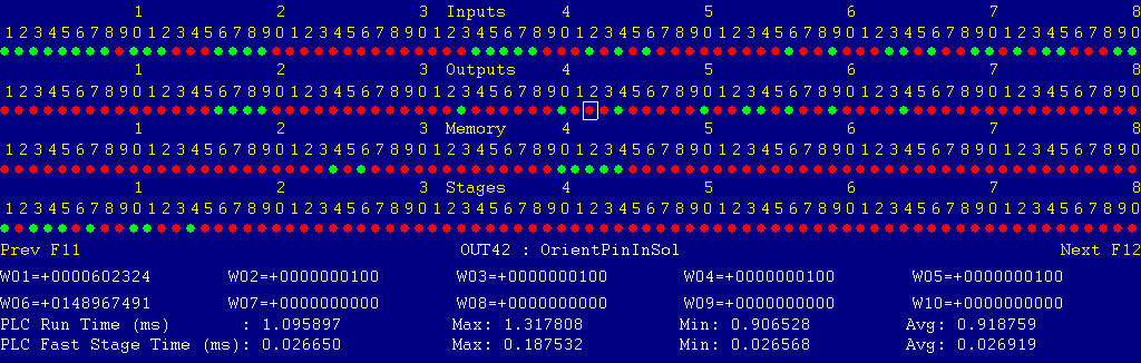
Each page of the Diagnostic display shows four rows of red and green dots: the first row shows PLC inputs 1 through 80; the second row PLC outputs 1 through 80; the third row PLC memory bits 1 through 80; and the fourth row PLC program stages 1 through 80.
You can use the arrow keys to move a highlight box over any of these locations. The name of the highlighted location will be displayed in the center of the screen below the red and green dots.
For example, in the illustration above the highlight box is on Output #42: The dot below the 2, to the right of the superscript 4, on the second line.
Below the four rows of bit status information are ten numeric ("word") variable values, labeled W1 through W10. Some of these variables also hold useful status information, described with the error and fault conditions to follow.
There are multiple pages of Diagnostic data. With the Alt-I diagnostic display showing, you can use the F12 and F11 keys to scroll right and left. For example, pressing F12 once will shift to the page showing inputs and outputs 81 through 160, and word variables W11 through W20.
Messages with 9000-series message numbers are Faults. After resolving the problem, you must press and release the Emergency Stop button to clear a Fault.
Messages with 8000-series message numbers are Errors. Errors will cancel the program cycle and stop the spindle and coolant, but they do not then need to be explicitly reset.
Messages with 5000-series and 2000-series message numbers are Warnings and Informational Messages. They do not cancel the cycle or require any action to reset.
In some cases, it will be necessary to open the control cabinet doors while power is on. For example, servo drive and spindle drive fault conditions can be more readily identified using the codes displayed on, or stored in, the drive units themselves.
WARNING: Use appropriate caution when working in the control cabinets
while power is on. Lethal voltages, up to 240VAC and 360VDC, are
present on many components.
The control detected an internal error in processing the PLC logic program.
Report this error to your dealer, along with the values from W14 and W15. Also report what function the machine was performing when the fault occurred.
You must shut down and cycle the power to clear this fault.
References:
PLC W14: Copy of internal SV_PLC_FAULT_STATUS, indicating the type of problem
PLC W15: Copy of internal SV_PLC_FAULT_ADDRESS, indicating the location of the problem
One of the servo amplifiers is reporting a fault condition.
If possible, check the LED display on the amplifier itself, in the right-hand cabinet, to see the specific fault code.
See the Yaskawa Sigma 7 series user manual for detailed fault information.
Press and release Emergency Stop to clear the fault.
References:
PLC MEM16: Axis #1 (X axis) drive status.  Green = okay, Red = fault
PLC MEM17: Axis #2 (Y axix) drive status.  Green = okay, Red = fault
PLC MEM18: Axis #3 (Z axis) drive status.  Green = okay, Red = fault
Schematic: Lines 10, 15, 20
The A1000 spindle drive (VFD) is reporting a fault condition.
This may result from over-voltage while decelerating, from overload during spindle reversal (e.g. in a tapping cycle), or from any number of other conditions.
If the cause is not immediately evident, then check the LCD display on the spindle drive itself, in the left-hand cabinet.
You can review past drive fault conditions using the A1000 drive's monitor menu. The ten most recent fault codes are in monitor parameters U3-01 through U3-10. See section 5.11 and appendix B of the A1000 drive manual.
References:
PLC INP10: Spindle drive fault signal:  Green = 1 = Okay, Red = 0 = Fault
Schematic: Lines 7, 125
The control unit detected loss of communication from the operator panel in the console.
Check for damage or disturbance to the cables between the console and the RedOak control unit in the control cabinet.
Press and release Emergency Stop to clear the fault.
References:
Schematic: Lines 90, 102
The operator panel reported back to the control unit a loss of communication from the control unit. This indicates the return signal from the operator panel is functioning normally, but the outgoing signal may have problems.
Check for damage or disturbance to the cables between the console and the RedOak control unit in the control cabinet.
Press and release Emergency Stop to clear the fault.
References:
Schematic: Lines 90, 102
The float switch FS1 closed, indicating that the way lube tank is low on oil. This is a Fault condition if it happens while no program cycle is running (see "5052 Warning..." below).
Check and refill the lube reservoir.
Press and release Emergency Stop to clear the fault.
References:
PLC INP34: FS1 inverted status.  Green = level okay, Red = level low
Schematic: Line 132
You exited the CNCM control software without first pressing Emergency Stop.
Always press Emergency Stop prior to exiting the control software.
Press and release Emergency Stop to clear the fault.
"9041 Hydraulic Pump Motor Overload"
The hydraulic pump motor tripped its circuit protector (MMS3).
Check the MMS, in the middle of the right panel, for a trip indication. If the MMS is tripped or turned off, then the red lever will be in flat, and the black lever will be sticking out.
Check the hydraulic pump and reservoir for possible causes of overload.
Press the black ON lever in to reset the MMS. You may have to wait several minutes for the overload to cool before it can be reset.
Press and release emergency stop to clear the fault condition.
References:
PLC INP11: Trip indication from MMS3.  Green = 1 = On and okay, Red = 0 = Off or tripped
Schematic: Lines 25, 126
The coarse feed motor for crossrail control tripped its circuit protector (MMS4).
Check the MMS, in the middle of the right panel, for a trip indication. If the MMS is tripped or turned off, then the red lever will be in flat, and the black lever will be sticking out.
Check the crossrail drive train for possible causes of overload.
Press the black ON lever in to reset the MMS. You may have to wait several minutes for the overload to cool before it can be reset.
Press and release emergency stop to clear the fault condition.
References:
PLC INP12: Trip indication from MMS4.  Green = 1 = On and okay, Red = 0 = Off or tripped
Schematic: Lines 27, 126
The fine feed motor for crossrail control tripped its circuit protector (MMS5).
Check the MMS, in the middle of the right panel, for a trip indication. If the MMS is tripped or turned off, then the red lever will be in flat, and the black lever will be sticking out.
Check the crossrail drive train for possible causes of overload.
Press the black ON lever in to reset the MMS. You may have to wait several minutes for the overload to cool before it can be reset.
Press and release emergency stop to clear the fault condition.
References:
PLC INP13: Trip indication from MMS5.  Green = 1 = On and okay, Red = 0 = Off or tripped
Schematic: Lines 29, 127
The flood coolant pump motor tripped its circuit protector (MMS6).
Check the MMS, in the middle of the right panel, for a trip indication. If the MMS is tripped or turned off, then the red lever will be in flat, and the black lever will be sticking out.
Check the coolant pump and tank for possible causes of overload.
Press the black ON lever in to reset the MMS. You may have to wait several minutes for the overload to cool before it can be reset.
Press and release emergency stop to clear the fault condition.
References:
PLC INP11: Trip indication from MMS6.  Green = 1 = On and okay, Red = 0 = Off or tripped
Schematic: Lines 31, 127
The headstock lube pump motor tripped its circuit protector (MMS7).
Check the MMS, in the middle of the right panel, for a trip indication. If the MMS is tripped or turned off, then the red lever will be in flat, and the black lever will be sticking out.
Check the gear lube pump and headstock sump for possible causes of overload.
Press the black ON lever in to reset the MMS. You may have to wait several minutes for the overload to cool before it can be reset.
Press and release emergency stop to clear the fault condition.
References:
PLC INP15: Trip indication from MMS7.  Green = 1 = On and okay, Red = 0 = Off or tripped
Schematic: Lines 33, 128
The axis way lube pump motor tripped its circuit protector (MMS8).
Check the MMS, in the middle of the right panel, for a trip indication. If the MMS is tripped or turned off, then the red lever will be in flat, and the black lever will be sticking out.
Check the lube pump and reservoir for possible causes of overload.
Press the black ON lever in to reset the MMS. You may have to wait several minutes for the overload to cool before it can be reset.
Press and release emergency stop to clear the fault condition.
References:
PLC INP16: Trip indication from MMS8.  Green = 1 = On and okay, Red = 0 = Off or tripped
Schematic: Lines 35, 128
The coolant scavenger pump motor tripped its circuit protector (MMS9).
Check the MMS, in the middle of the right panel, for a trip indication. If the MMS is tripped or turned off, then the red lever will be in flat, and the black lever will be sticking out.
Check the scavenger pump for possible causes of overload.
Press the black ON lever in to reset the MMS. You may have to wait several minutes for the overload to cool before it can be reset.
Press and release emergency stop to clear the fault condition.
References:
PLC INP33: Trip indication from MMS9.  Green = 1 = On and okay, Red = 0 = Off or tripped
Schematic: Lines 37, 132
The hydraulic pump is running, but the hydraulic pressure switch PS1 indicates inadequate hydraulic pressure.
Check the hydraulic power unit for possible causes of pressure loss.
Press and release emergency stop to clear the fault condition.
References:
Machine Parameter 750: Hydraulic startup time, before pressure is expected (ms)
Machine Parameter 751: Pressure drop-out tolerance, before reporting a fault (ms)
PLC INP82: Pressure indication from PS1.  Green = 1 = Pressure okay, Red = 0 = Low or no pressure
Schematic: Lines 25, 170
The thermal switch TH1, in the hydraulic tank, closed to indicate that the oil temperature is too high.
Check the hydraulic system for possible causes of overheating.
Allow time for the tank to cool.
Press and release emergency stop to clear the fault condition.
References:
PLC INP81: Thermal switch TH1.  Green = 1 = Temperature high, Red = 0 = Temperature okay
Schematic: Line 170
The control lost communication with one of the PLC I/O expansion boards.
Open the control cabinets and check the LED1 status LED on each of the PLCEXP1616 boards, at the top of the right panel.
In normal operation, each LED1 should show a repeating sequence of horizontal bars.
If LED1 is not lit, check the connections at both ends of the green CAT5 cable which connects PLC ports on the RedOak unit to the PLCADD1616 board.
If LED1 shows a flashing number, see the PLCEXP1616 hardware manual, in the Component Manuals folder on the control's hard drive.
References:
PLC W36: bitmap of detected PLC expansion boards.  15 = four boards detected
Machine Parameter 900: bitmap of expected PLC expansion boards.  15 = four boards expected
Schematic: Lines 104, 105, 131, 145, 156, 169
The control cabinet air conditioner is not running.
This may be due to failure of the air conditioning unit, or due to circuit breaker CB7 having tripped.
This condition is also triggered when the control cabinet door is open, because door switch LS0 shuts off the air conditioner. In that case there is nothing wrong with the air conditioner, and this fault can be ignored.
References:
PLC INP80: Air-conditioner running feedback: Green = 1 = running, Red = 0 = not running
Schematic: Lines 58, 164
The thermal switch TH2 in the regenerative braking resistor, outside the right wall of the cabinet, opened to indicate that the resistor is overheating.
Allow time for the resistor unit to cool down, and the thermal switch to close again.
Press and release emergency stop to clear the fault condition.
References:
PLC INP35: Brake resistor thermal switch TH2: Green = 1 = Okay,  Red = 0 = Overheat
Schematic: Lines 2, 133
The thermal switch THS1 in the spindle motor opened to indicate that the motor is overheating.
Allow time for the motor to cool down, and for the thermal switch to close again.
Press and release Emergency Stop to clear the fault.
Verify that the spindle motor cooling fan runs whenever the spindle motor is running, and that the cooling air passages are not blocked.
References:
PLC INP79: Spindle motor thermal switch TH3: Green = closed = Okay,  Red = open = Overheat
PLC OUT3: Spindle motor cooling fan relay: Green = On, Red = Off
Schematic: Lines 3, 60, 164, 184
Float switch FS4 closed, to indicate that the hydraulic oil level in the hydraulic tank is low.
Check the oil level in the tank. Check for significant leaks in the hydraulic power unit and in the hydraulic components on the tool changer and in the head.
References:
PLC INP93: Hydraulic oil float switch FS4: Green = closed = Low level,  Red = open = Level okay
Schematic: Line 176
The spindle tool-clamped and the tool-unclamped switches were both closed at the same time.
This indicates faulty or stuck switches, or damaged wiring.
References:
PLC INP67: Tool-clamped switch LS7.  Green = closed = fully clamped.  Red = open = not fully clamped
PLC INP68: Tool-unclamped switch LS8.  Green = closed = fully unclamped.  Red = open = not fully unclamped
Schematic: Line 158
The ATC arm-up and the arm-down switches were both closed at the same time.
This indicates faulty or stuck switches, or damaged wiring.
References:
PLC INP45: Arm-down switch LS26.  Green = closed = arm fully down.  Red = open = not fully down
PLC INP46: Arm-up switch LS27.  Green = closed = arm fully up.  Red = open = not fully up
Schematic: Line 138
Two or more of the ATC arm carrier position switches were closed at the same time.
This indicates faulty or stuck switches, or damaged wiring.
References:
PLC INP47: Arm-left switch LS28.  Green = closed = carrier to left.  Red = open = not fully left
PLC INP48: Arm-right switch LS29.  Green = closed = carrier to right.  Red = open = not fully right
PLC INP60: Arm-right switch LS33.  Green = closed = carrier in middle.  Red = open = not in middle
Schematic: Lines 139, 151
The ATC arm-CW and the arm-CCW rotation switches were both closed at the same time.
This indicates faulty or stuck switches, or damaged wiring.
References:
PLC INP43: Arm-CCW switch LS24.  Green = closed = arm rotated to CCW stop.  Red = open = not at CCW stop
PLC INP44: Arm-CW switch LS25.  Green = closed = arm rotated to CW stop.  Red = open = not at CW stop
Schematic: Line 137
You attempted to start an automatic program cycle, but Maintenance Mode (Aux12) is still active.
Press and hold the Aux12 key for one second to cancel Maintenance Mode.
"8205 CANNOT TURN SPINDLE WITH TOOL UNCLAMPED"
You attempted to start, run, or orient the spindle, but the spindle drawbar is still open.
Turn the tool-release button CCW to the Clamp position, and press the button to clamp the drawbar.
References:
PLC OUT53: Spindle drawbar unclamp solenoid: Green = On = unclamp
PLC INP67: Tool-clamped switch LS7: Green = 1 = tool clamped, Red = 0 = tool not clamped
PLC INP68: Tool-unclamped switch LS8: Green = 1 = tool unclamped, Red = 0 = tool not unclamped
PLC MEM27: Manual tool-unclamp request: Green = 1 = manual unclamp active, Red = 0 = manual unclamp not active
Schematic: Lines 158, 221
The spindle was running and the spindle oil mist lubrication solenoid was on, but the oil mist air pressure switch PS2 indicates inadequate pressure.
Check the air supply to the spindle head, and check solenoid valve function.
Note that the solenoid valve is only turned on when the spindle starts, and will be turned off when this error occurs. If there is a persistent problem with the air pressure or switch, then the solenoid will only remain on for one second after you start the spindle; then both the spindle and the solenoid will be turned off.
References:
PLC OUT49: Spindle oil mist solenoid SOL11: Green = On, Red = Off
PLC INP69: Oil mist pressure switch PS2: Green = 1 = pressure, Red = 0 = low or no pressure
Schematic: Lines 159, 217
The spindle was running and the spindle oil mist lubrication solenoid was on, but float switch FS2 closed, to indicate that the reservoir is low on oil.
References:
PLC INP70: Float switch FS2: Green = 1 = oil level low, Red = 0 = level okay
Schematic: Line 159
During an automatic program cycle, with no tool change in progress, the signal from the CNC to the PLC which reports that initial head positioning for a tool change is complete was set (1). This flag should only be set for short intervals during a tool change.
Report this condition to your dealer.
"8212 ATC NOT READY: TOOL CLAMP INP"
During an automatic program cycle, with no tool change in progress, the spindle tool-clamped switch was open.
This indicates either a malfunctioning or out-of-position switch, or an uncommanded tool release.
References:
PLC INP67: Tool-clamped switch LS7.  Green = closed = fully clamped.  Red = open = not fully clamped
Schematic: Line 158
During an automatic program cycle, with no tool change in progress, the spindle tool-unclamped switch was closed.
This indicates either a malfunctioning or out-of-position switch, or an uncommanded tool release.
References:
PLC INP68: Tool-unclamped switch LS8.  Green = closed = fully unclamped.  Red = open = not unclamped
Schematic: Line 158
During a program cycle, with no automatic tool change in progress, the tool changer arm was not in its fully-up position.
Use the ATC Control Pendant to move the arm back up.
References:
PLC OUT69: Changer arm up solenoid: Green = On = drive arm up
PLC INP46: Arm-up switch LS27: Green = 1 = arm up, Red = 0 = arm not up
PLC MEM99: Arm-down request: Green = 1 = drive arm down, Red = 0 = drive arm up
Schematic: Lines 138, 245
During a program cycle, with no automatic tool change in progress, the tool changer arm was in its fully-down position.
Use the ATC Control Pendant to move the arm back up.
References:
PLC OUT69: Changer arm up solenoid: Green = On = drive arm up
PLC OUT70: Changer arm down solenoid: Green = On = drive arm down
PLC INP45: Arm-down switch LS26: Green = 1 = arm down, Red = 0 = arm not down
PLC MEM99: Arm-down request: Green = 1 = drive arm down, Red = 0 = drive arm up
Schematic: Lines 138, 245, 246
During a program cycle, with no automatic tool change in progress, the tool changer arm carrier was not in the middle position.
Use the ATC Control Pendant to move the carrier back to center.
References:
PLC OUT71: Changer arm left solenoid: Green = On = drive arm left
PLC OUT72: Changer arm right solenoid: Green = On = drive arm right
PLC INP60: Arm-middle switch LS33: Green = 1 = arm in middle, Red = 0 = arm not in middle
Schematic: Lines 151, 247, 248
During a program cycle, with no automatic tool change in progress, the tool changer arm carrier was in the left position, under the magazine.
Use the ATC Control Pendant to move the carrier back to center.
References:
PLC OUT71: Changer arm left solenoid: Green = On = drive arm left
PLC OUT72: Changer arm right solenoid: Green = On = drive arm right
PLC INP47: Arm-right switch LS28: Green = 1 = arm to left, Red = 0 = arm not to left
PLC INP60: Arm-middle switch LS33: Green = 1 = arm in middle, Red = 0 = arm not in middle
Schematic: Lines 139, 151, 247, 248
During a program cycle, with no automatic tool change in progress, the tool changer arm carrier was in the right-side position, under the spindle.
Use the ATC Control Pendant to move the carrier back to center.
References:
PLC OUT71: Changer arm left solenoid: Green = On = drive arm left
PLC OUT72: Changer arm right solenoid: Green = On = drive arm right
PLC INP48: Arm-right switch LS29: Green = 1 = arm to right, Red = 0 = arm not to right
PLC INP60: Arm-middle switch LS33: Green = 1 = arm in middle, Red = 0 = arm not in middle
Schematic: Lines 139, 151, 247, 248
During a program cycle, with no automatic tool change in progress, the tool changer arm neither fully CW nor fully CCW, and therefore not aligned with the spindle and the magazine.
Use the ATC Control Pendant to rotate the arm to one stop or the other (it does not matter which).
References:
PLC OUT67: Changer arm CCW solenoid: Green = On = rotate arm CCW
PLC OUT68: Changer arm CW solenoid: Green = On = rotate arm CW
PLC INP43: Arm-CCW switch LS24: Green = 1 = arm fully CCW, Red = 0 = arm not fully CCW
PLC INP44: Arm-CW switch LS25: Green = 1 = arm fully CW, Red = 0 = arm not fully CW
Schematic: Lines 137, 243, 244
You, or the CNC program, requested an automatic tool change, but the Auto/Man selector on the ATC Pendant was in the Manual position.
Switch the ATC Pendant to Auto mode, then try the operation again.
References:
PLC INP84: ATC Pendant Auto/Man selector: Green = 1 = Auto, Red = 0 = Manual
Schematic: Line 171
During an automatic tool change, the control needed to rotate the tool carousel to the new tool or to the put-back position for the previous tool, but the Hand/Auto toggle switch on the Magazine Control Panel was in manual (hand) mode.
Switch the Magazine Panel switch to Auto mode, then try the operation again.
References:
PLC INP41: Magazine Hand/Auto selector: Green = 1 = Auto, Red = 0 = Manual
Schematic: Line 136
At the beginning of an automatic tool change, the PLC was waiting for the CNC to move the Y and Z axes into position, but the CNC did not report that the move was complete within the expected time.
Check for any conditions that might pause or excessively slow down axis movement.
Check that the time limit in Parameter 720 is set appropriately.
References:
Machine Parameter 720: Maximum time for Y and Z movement to tool-change position (ms)
During an automatic tool change, the carousel (magazine) did not complete its rotation to the new tool location within the expected time.
Check for any condition that might interfere with carousel rotation.
Check that the positions read from the carousel encoder are valid and consistently updated as the carousel rotates.
Check that the target position for the new tool was correctly sent to the PLC and stored in variable W18.
Check that the time limit in Parameter 721 is set appropriately.
References:
PLC OUT65: Carousel forward rotation solenoid SOL21: Green = On = rotate
PLC OUT66: Carousel reverse rotation solenoid SOL22: Green = On = back up and stop against pawl
PLC INP49-INP56: Magazine position BCD encoder: Green = 1 = bit active, Red = 0 = bit inactive
PLC W17: Current carousel position read from the encoder (1-24)
PLC W18: Target position (new tool number)
Machine Parameter 721: Maximum time for carousel to rotate to any tool position (ms)
Schematic: Lines 146-149, 241, 242
During an automatic tool change, the spindle orientation process did not complete within the expected time.
Verify that the transmission is in high gear.
Check for possible interference with the orient proximity sensor or its signal-combining circuit SC1.
Check that the time limit in Parameter 722 is set appropriately.
References:
PLC OUT6: Spindle orient command to VFD: Green = On = orient
PLC OUT7: Spindle run enable to VFD: Green = On = run
PLC INP9: Orient completion signal from VFD: Green = 1 = complete, Red = 0 = not complete
Machine Parameter 722: Maximum time for spindle to orient (ms)
Schematic: Lines 5, 7, 8, 114, 125, 187
During an automatic tool change, while attempting to unclamp the previous tool from the spindle, the spindle drawbar tool-unclamped switch did not close within the expected time.
Use the ATC Control Pendant to move the arm back to center, standing by to catch the tool if it fails to remain in the spindle. Then manually unclamp and reclamp the tool holder.
If the drawbar fails to open and close normally, then investigate possible issues with the hydraulic solenoid valves and cylinder.
If the drawbar opens normally, but the tool-unclamped switch does not close, check switch adjustment and function.
Also check the condition of incidental components. In order to proceed from the tool-unclamping stage, not only must the tool-unclamped switch close, but:
PLC word variable W8, and the AWDecode utility, will allow you to check whether any of those conditions caused the failure.
References:
PLC OUT53: Spindle drawbar unclamp solenoid: Green = On = unclamp
PLC INP43: Arm-CCW switch LS24: Green = 1 = arm fully CCW, Red = 0 = arm not fully CCW
PLC INP44: Arm-CW switch LS25: Green = 1 = arm fully CW, Red = 0 = arm not fully CW
PLC INP48: Arm-right switch LS29: Green = 1 = arm to right, Red = 0 = arm not to right
PLC INP68: Tool-unclamped switch LS8: Green = 1 = tool unclamped, Red = 0 = tool not unclamped
PLC MEM34: Spindle orient completion flag: Green = 1 = oriented, Red = 0 = not oriented
PLC W8: Bitmap of tool change input and flag states.  Use AWDecode to interpret
Machine Parameter 729: allowed time for drawbar to unclamp tool (milliseconds)
Schematic: Lines 137, 139, 158, 221
During an automatic tool change, while attempting to clamp the new tool in the spindle, the spindle drawbar tool-clamped switch did not close within the expected time.
Check whether the tool is properly seated. If the drawbar fingers fail to fully engage the pull stud, then the drawbar may not close all the way.
Use the ATC Control Pendant to move the arm back to center, standing by to catch the tool if it fails to remain in the spindle. Then manually unclamp and reclamp the tool holder.
If the drawbar fails to open and close normally, then investigate possible issues with the hydraulic solenoid valves and cylinder.
If the drawbar opens and closes normally, but the tool-clamped switch does not close, check switch adjustment and function.
Also check the condition of incidental components. In order to proceed from the tool-clamping stage, not only must the tool-clamped switch close, but:
PLC word variable W8, and the AWDecode utility, will allow you to check whether any of those conditions caused the failure.
References:
PLC OUT53: Spindle drawbar unclamp solenoid: Green = On = unclamp
PLC INP43: Arm-CCW switch LS24: Green = 1 = arm fully CCW, Red = 0 = arm not fully CCW
PLC INP44: Arm-CW switch LS25: Green = 1 = arm fully CW, Red = 0 = arm not fully CW
PLC INP48: Arm-right switch LS29: Green = 1 = arm to right, Red = 0 = arm not to right
PLC INP67: Tool-clamped switch LS7: Green = 1 = tool clamped, Red = 0 = tool not clamped
PLC MEM34: Spindle orient completion flag: Green = 1 = oriented, Red = 0 = not oriented
PLC W8: Bitmap of tool change input and flag states.  Use AWDecode to interpret
Machine Parameter 731: allowed time for drawbar to clamp tool (milliseconds)
Schematic: Lines 137, 139, 158, 221
During an automatic tool change, while attempting to move the changer arm down to remove the old tool from the spindle, the changer arm failed to move down within the expected time.
If the arm failed to move down at all, it is possible that the drawbar failed to open and release the tool. Investigate possible issues with the hydraulic solenoid valves or cylinder.
Also check the condition of incidental components. In order to proceed from the arm-down stage, not only must the arm-down switch close, but:
PLC word variable W8, and the AWDecode utility, will allow you to check whether any of those conditions caused the failure.
References:
PLC OUT70: Changer arm down solenoid: Green = On = drive arm down
PLC INP43: Arm-CCW switch LS24: Green = 1 = arm fully CCW, Red = 0 = arm not fully CCW
PLC INP44: Arm-CW switch LS25: Green = 1 = arm fully CW, Red = 0 = arm not fully CW
PLC INP45: Arm-down switch LS26: Green = 1 = arm down, Red = 0 = arm not down
PLC INP48: Arm-right switch LS29: Green = 1 = arm to right, Red = 0 = arm not to right
PLC INP68: Tool-unclamped switch LS8: Green = 1 = tool unclamped, Red = 0 = tool not unclamped
PLC MEM34: Spindle orient completion flag: Green = 1 = oriented, Red = 0 = not oriented
PLC MEM99: Arm-down request: Green = 1 = drive arm down, Red = 0 = drive arm up
PLC W8: Bitmap of tool change input and flag states.  Use AWDecode to interpret
Machine Parameter 725: allowed time to move the arm down (milliseconds)
Schematic: Lines 137-139, 158, 246
During an automatic tool change, while attempting to move the changer arm up to insert the new tool into the spindle, the changer arm failed to move all the way up within the expected time.
If the arm moved up, but did not get the tool fully seated in the spindle, it is possible that the drawbar failed to remain open to accept the tool. Investigate possible issues with the hydraulic solenoid valves or cylinder.
Also check the condition of incidental components. In order to proceed from the arm-up stage, not only must the arm-up switch close, but:
PLC word variable W8, and the AWDecode utility, will allow you to check whether any of those conditions caused the failure.
References:
PLC OUT69: Changer arm up solenoid: Green = On = drive arm up
PLC INP43: Arm-CCW switch LS24: Green = 1 = arm fully CCW, Red = 0 = arm not fully CCW
PLC INP44: Arm-CW switch LS25: Green = 1 = arm fully CW, Red = 0 = arm not fully CW
PLC INP45: Arm-down switch LS26: Green = 1 = arm down, Red = 0 = arm not down
PLC INP48: Arm-right switch LS29: Green = 1 = arm to right, Red = 0 = arm not to right
PLC INP68: Tool-unclamped switch LS8: Green = 1 = tool unclamped, Red = 0 = tool not unclamped
PLC MEM34: Spindle orient completion flag: Green = 1 = oriented, Red = 0 = not oriented
PLC MEM99: Arm-down request: Green = 1 = drive arm down, Red = 0 = drive arm up
PLC W8: Bitmap of tool change input and flag states.  Use AWDecode to interpret
Machine Parameter 725: allowed time to move the arm down (milliseconds)
Schematic: Lines 137-139, 158, 245
During an automatic tool change, while preparing to return the old tool to the carousel, sensor PRX-1 indicated that there was already a tool holder in the carousel position that the old tool is supposed to go into.
Check whether the carousel is indeed stopped at the correct position.
Check whether there really is a misplaced tool holder in that position.
Use manual magazine and ATC controls to remove any unexpected too holder, and to either return the tool which was just removed from the spindle to its place in the carousel; or return that tool to the spindle, and put the newly-loaded tool back in its place in the carousel.
References:
PLC INP42: Tool sensor PRX-1: Green = 1 = tool detected in carousel, Red = 0 = no tool detected
PLC W17: Current carousel position reading (1-24)
Schematic: Line 136
The specified axis was moving while its clamp was still applied. This is usually a CNC programming error: the CNC program failed to release the clamp before repositioning the axis. See the Axis Clamps section for a list of M functions and a CNC programming example.
The tolerance for servo motor movement with the clamp applied is set by parameters.
References:
Machine Parameter 744: axis-clamped movement tolerance for Y axis, motor encoder counts
Machine Parameter 745: axis-clamped movement tolerance for Z axis, motor encoder counts
Your CNC program called for spindle start with M3 or M4, but spindle control is in Manual mode.
Press the spindle AUTO/MAN key to switch back to Auto mode, then
press Cycle Start to resume running the program.
"4054 Select Auto Coolant, press CYCLE START"
Your CNC program called for coolant with M7 or M8, but coolant control is in Manual mode.
Press the coolant AUTO/MAN key to switch back to Auto mode, then
press Cycle Start to resume running the program.
"5052 Warning: Lube Low"
The float switch FS1 opened, indicating that the way lube tank is low on oil.
This happened while a program cycle was running, so the control only displays a warning message instead of triggering a 9036 Fault condition.
Check and refill the lube reservoir.
References:
PLC INP34: FS1 inverted status.  Green = level okay, Red = level low
Schematic: Line 132
You attempted to jog the Y axis, but the Y axis clamp is applied.
Use M35 to unclamp the Y axis, then jog the axis as needed.
"5056 Z Axis is Clamped: Jogging Prohibited"
You attempted to jog the Z axis, but the Z axis clamp is applied.
Use M47 to unclamp the Z axis, then jog the axis as needed.
"5057 Crossrail-Up Limit Tripped"
You attempted to move the crossrail up, but its upper limit switch LS21 is tripped.
If the crossrail is not actually at its upper limit, then check for interference with the limit switch, or for loose or damaged wiring.
References:
PLC INP38: Limit switch LS21 status.  Green = closed = okay, Red = open = tripped
Schematic: Line 134
You attempted to move the crossrail down, but its lower limit switch LS22 is tripped.
If the crossrail is not actually at its lower limit, then check for interference with the limit switch, or for loose or damaged wiring.
References:
PLC INP39: Limit switch LS22 status.  Green = closed = okay, Red = open = tripped
Schematic: Line 135
The PLC program requested display of a message on the screen, but the provided message code was not valid.
This indicates an error in the PLC program. Report the message to your dealer, along with the value in PLC variable W16.
References:
PLC W16: stores the invalid message code
The PLC hardware detected the presence of an I/O expansion board, but the setting of Machine Parameter 900 did not tell it to expect that board in the system.
On this machine, there should be four I/O expansion boards installed, and Machine Parameter 900 should be set to 15.0.
References:
PLC W36: bitmap of detected PLC expansion boards.  15 = four boards detected
Machine Parameter 900: bitmap of expected PLC expansion boards.  15 = four boards expected
The CNC program called for magazine pre-rotation to an upcoming tool position, but the toggle switch on the Magazine Panel is switched to Manual (hand) mode.
References:
PLC INP41: Magazine Hand/Auto selector: Green = 1 = Auto, Red = 0 = Manual
Schematic: Line 136
You attempted to rotate the carousel or use the load station foot switch to unclamp a tool, but the toggle switch on the Magazine Panel is switched to Auto mode.
Wait for any programmed carousel rotation to finish, then switch the Magazine Panel to Manual (hand) mode and try the operation again.
References:
PLC INP41: Magazine Hand/Auto selector: Green = 1 = Auto, Red = 0 = Manual
Schematic: Line 136
A previous servo drive fault condition has been resolved,
and cleared with Emergency Stop.
"2024 PLC Faults Cleared"
A previous PLC fault condition has been resolved,
and cleared with Emergency Stop.
"2035 KEYBOARD JOGGING DISABLED"
You inadvertently pressed a keyboard combination that is
used for keyboard jogging controls, but keyboard jogging
features have been disabled on this machine.
"2099 Message Cleared"
A previous fault condition has been cleared with Emergency Stop.
The order of the axis drives; order of the axis definitions in the control configuration menus; and order of the axis jogging controls can vary. Definitions for this machine are as follows:
| Axis | Axis # | Drive # | Drive-Okay Bit | Jog Keys | MPG Position |
|---|---|---|---|---|---|
| X | 1 | 1 | MEM16 | X | 1 (X) |
| Y | 2 | 2 | MEM17 | Y | 2 (Y) |
| Z | 3 | 3 | MEM18 | Z | 3 (Z) |
26-Aug-2026 MBL
